Statement of the problem of designing a liquid rocket engine dual bell nozzle of the maximum thrust using the direct method of the calculus of variations
Ivan Dubrovskyi
Oles Honchar Dnipro National University, Dnipro
Valerii Bucharskyi
Oles Honchar Dnipro National University, Dnipro
Introduction
A rocket engine with a standard single-section profiled nozzle provides maximum thrust only at a certain value of atmospheric pressure [1]. To expand the range of atmospheric pressure values at which the optimum engine operation mode is achieved, a dual bell nozzle can be used [2]. A typical diagram of such a nozzle is shown in Fig. 1. Its main elements are three cross-sections a, b, c and two profiled section elements a-b, b-c bounded by them. The fig. 1 shows the general case of the contour of such a nozzle, for which a corner in the generatrix is located at points a and b. In addition, the section a coincides with the critical section of the engine chamber.
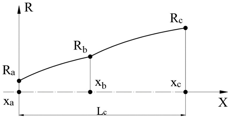
Figure 1 – Dual bell nozzle contour
Let’s consider the principle of operation of such a nozzle. When operating at low altitude, with a high value of atmospheric pressure pe1, the thrust is generated only by the first profiled section a–b. With an increase in flight altitude and a corresponding drop in atmospheric pressure to pe2 (pe1 > pe2), the flow of combustion products expands, begins to flow around the second profiled section and create additional thrust. Thus, an engine with a dual bell nozzle will generate more average flight time thrust than an engine with a single nozzle designed to operate at one of the atmospheric pressures pe1 or pe2.
Usually, the method of characteristics [3] is used for profiling a dual bell nozzle. However, it has the following disadvantages:
- the inability to profile the maximum thrust nozzle with explicit restrictions on its dimensions, weight, etc.;
- the requirement for the absence of shock waves in the flow of combustion products inside the nozzle.
As an alternative to the method of characteristics, this paper proposes to use the direct method of calculus of variations [4] for profiling a dual bell nozzle.
The aim and tasks of the study
The aim of the work is to obtain the thrust functional for its further maximization using the direct method of the calculus of variations. To achieve this goal, it is necessary to solve the following tasks:
- determine the initial data necessary to derive the thrust functional and to implement its further maximization;
- derive the expression of the thrust functional.
Initial data
The initial data for the problem of profiling the axisymmetric dual bell nozzle by the direct method of the calculus of variations are:
- known contour of the subsonic part of the rocket engine chamber;
- mathematical model of combustion products used to describe their flow inside the nozzle;
- parameters of combustion products in the critical section: pressure, density and velocity vector;
- atmospheric pressure values at both engine operating modes pe1 and pe2,(pe1 > pe2).
As the main mathematical model describing the flow of combustion products in the liquid rocket engine chamber, a model of an inviscid compressible ideal gas of constant chemical composition was chosen, consisting of a system of stationary Euler equations (1), which was closed by the Mendeleev-Clapeyron equation of state [5]. System (1) is written in differential form in a cylindrical coordinate system under the assumption of axial symmetry of the flow of combustion products inside the LRE chamber.


where F – axial flux vector;
G – radial flux vector;
S – source term;
R – radius, m;
ρ – density, kg/m3;
p – pressure, Pa;
u – axial velocity, m/s;
v – radial velocity, m/s;
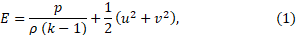
E – total energy, J/kg;
k – heat capacity ratio.
Thrust functional derivation
The thrust of an arbitrary axisymmetric nozzle can be defined as the resultant of the pressure forces applied to the side surface of the nozzle [1]:
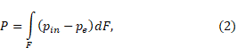
where P – thrust, H;
F – side surface area of a nozzle, m2;
pin – combustion products pressure inside the nozzle, Pa;
pe – atmospheric pressure at the given altitude, Pa.
Let us select on the nozzle contour an annular element with a width dx, a height dR and located at a distance R from the axis of symmetry of the nozzle (fig. 2).
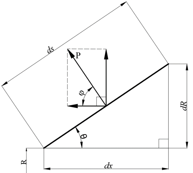
Figure 2 – Annual element of a nozzle contour
Its side surface area equals dF = 2πRds. Using this equality, the integral (2) can be represented as:
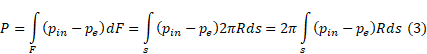
Due to the axial symmetry of the nozzle, all the radial components of the thrust will be mutually balanced, therefore, in what follows, we will take into account only its axial component. In view of this, expression (3) is transformed to the following form:
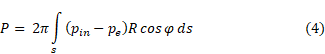
From the fig. 2 one can deduce that cosφ = cos(90-θ) = sinθ = dR/ds, and since R` = dR/dx, then rewrite (4) in this way:
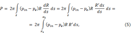
where x1 – the coordinate of the beginning of the nozzle at the horizontal axis, m;
x2 – the coordinate of the end of the nozzle at the horizontal axis, m;
R = R(x) – nozzle contour that is being designed.
Let’s transform the integrand from (5):
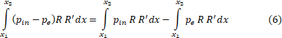
Since the atmospheric pressure does not depend on the integration variable, we take it out of the brackets and integrate the second term into (6):
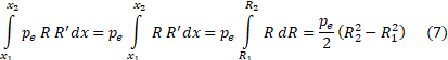
Let’s substitute (6) and (7) into (5). As a result, we get the final expression for determining the thrust of an arbitrary nozzle:
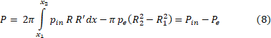
In (8), there are clearly two thrust components: an internal one, which depends on the pressure of the combustion products, and an external one, which depends only on the pressure of the atmosphere.
Now use (8) to calculate the thrust of the dual bell nozzle shown in
fig. 1. In the first operation mode with high atmospheric pressure pe1, only the first section of the nozzle a–b will create thrust, in the second mode – both sections a–b and b–c. Therefore, (8) for the second and the first mode will take the form (9):
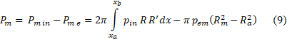
Here the number m can get values 1 and 2 depending on the mode, R1 = Rb, R2 = Rc.
Let’s combine the separate thrust equations taken from (9) to obtain the total thrust equation (10) for the both modes simultaneously. To do this, we introduce the coefficient α equal to 0 in the first mode and 1 in the second. Then the expression for the total thrust of the dual bell nozzle takes the form:

where α – the coefficient, that equals to 0 in the first operation mode and 1 – in the second;
PΣ – dual bell nozzle total thrust, H.
We will obtain the final form of the thrust functional by adding to (10) the restrictions imposed by the chosen mathematical model of combustion products (1). To do this, we use the Lagrange multipliers [6] – we introduce four unknown functions λ1, λ2, λ3, λ4, that depend on x and R, multiply them by the corresponding equations from the system (1) and sum them up:
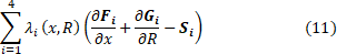
To add (11) to (10), we integrate (11) over the region K bounded from below by the axis of symmetry of the nozzle and from above by its contour. After that, the desired thrust functional will take the final form:
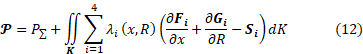
The values of functional (12) can only be obtained as a result of numerical simulation of the flow of combustion products in the chamber of a liquid rocket engine. To implement this, various numerical methods can be used [7, 8].
Conclusions
In the work, the initial data for the problem of profiling a dual bell nozzle were determined. An expression for the thrust functional was also obtained for such a nozzle. This will allow in the future to solve the problem of its maximization using the direct method of calculus of variations, the result of which will be the dual bell contour of the, producing the maximum thrust.
References
- Biblarz O., Sutton G. P. Rocket propulsion elements. Wiley & Sons, Incorporated, John, 2016. 792 p.
- Future space-transport-system components under high thermal and mechanical loads / ed. by N. A. Adams et al. Cham : Springer International Publishing, 2021. URL: https://doi.org/10.1007/978-3-030-53847-7 (date of access: 25.05.2023).
- Zucrow M. J., Hoffman J. D. Gas dynamics, vol. 2: multidimensional flow. John Wiley & Sons Inc, 1977. 490 p.
- Giusti E. Direct methods in the calculus of variations. River Edge, NJ : World Scientific, 2003. 403 p.
- Chorin A. J., Marsden J. E. Mathematical introduction to fluid mechanics. Springer London, Limited, 2013. 172 p.
- Kot M. A first course in the calculus of variations. Providence, Rhode Island : American Mathematical Society, 2014. 298 p.
- Dubrovskyi I., Bucharskyi V. Development of a method of extended cells for the formulation of boundary conditions in numerical integration of gas dynamics equations in the domains of a curvilinear shape. Eastern-European Journal of Enterprise Technologies. 2020. Vol. 5, No 7. P. 72-84.
- Ferziger J. H., Milovan P., Street R. L. Computational Methods for Fluid Dynamics. Germany: Springer-Verlag. 606 p